

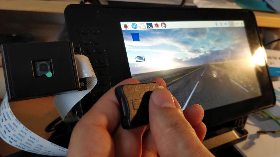
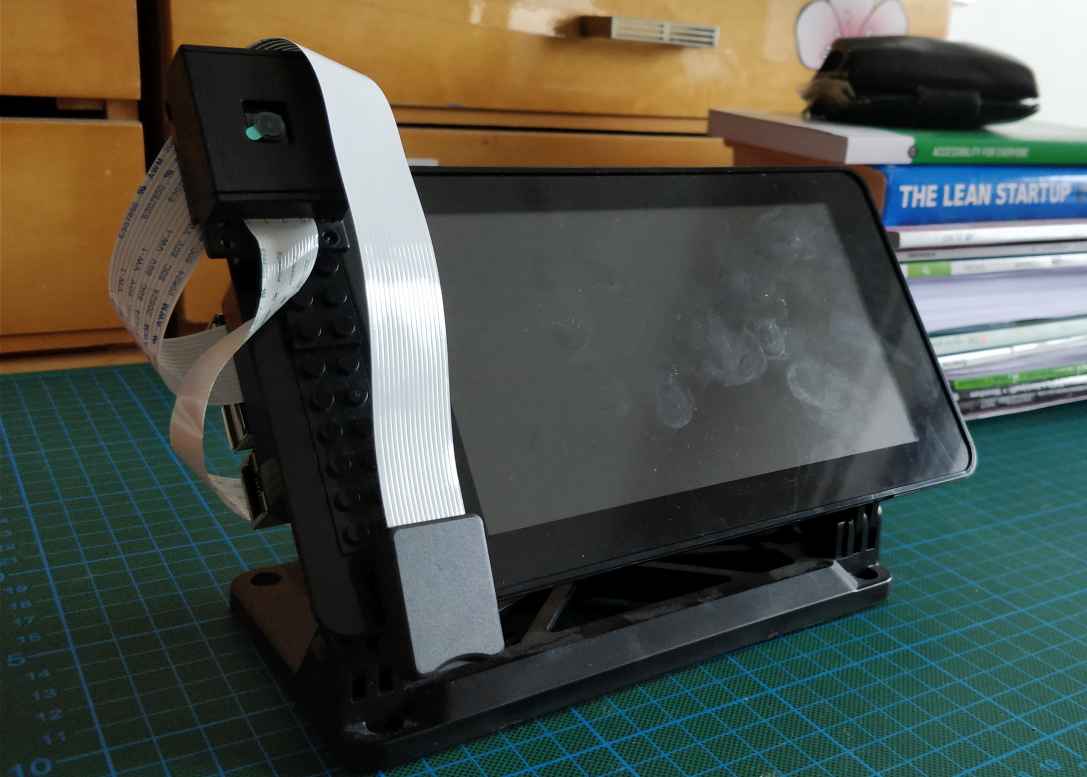
A few months ago, I bought the SmartiPi Touch Case in combination with the official 7″ Touchscreen Display for my Raspberry Pi 3. The setup was pretty easy and well documented. Especially, on YouTube and on this Online Shop are good setup tutorials available. So far so good, my first setup session worked fine. The case is solid and perfect for Rapid Prototype projects, which needs a small screen.
Unfortunately, after a while I figured out, that it would like to exchange the SD-Card more frequently. Maybe some of you have already read the product reviews. As cool as this case is, but the MicroSD-Card is only accessible through unmount again the whole Raspberry Pi. In some circumstance that is not very practical. Additionally, to have a second display output, for instance a HDMI output would be cool to. A second display output could boost the prototype process of some Kiosk, Smart Screen (e.g. MagicMirror), or other Media Entertainment applications (like Projection Mapping configuration on this touch screen) In that context, I tried to pimp/extend my SmartPi case with these two approaches:
- Easy replacable MicroSD Card Adapter
- Additional visual output via HDMI
In this blog post, I will describe some of my experiences. The MicroSD-Card Extension was after some failures successful. Unfortunately, I could not find a good solution for the HDMI output.
Adding a MicroSD Card Extension
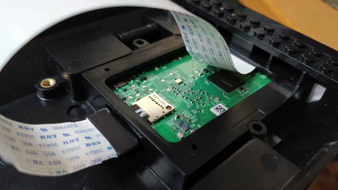
I bought two ordinary MicroSD Card Extender cables on Amazon. A short and a longer one allowed me to experiment with my needs. For my first test, I opened my SmartPi case and plugged the extender cable into my Raspberry Pi 3. The test went perfect and my Pi was able to work with this adapter cable without any problems.
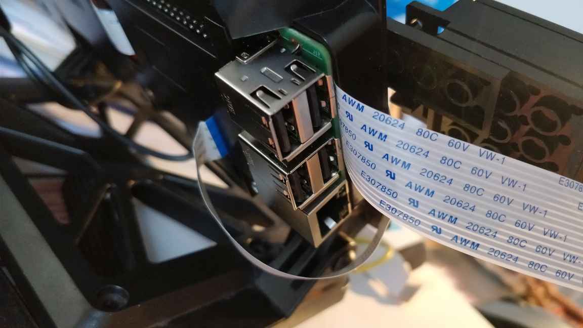
Fine, back to the next step, the Pi back has to get back into the SmartiPi Touch case. Unfortunately, I failed on my first try… The male plug of my adapter cable was too long. It got stuck somehow between the USB plug of the Touchscreen board and plastic separator of the case. I had to cut some plastic away, like you can see on the pictures.
Please be careful with the knife and wear glasses for eye protection!


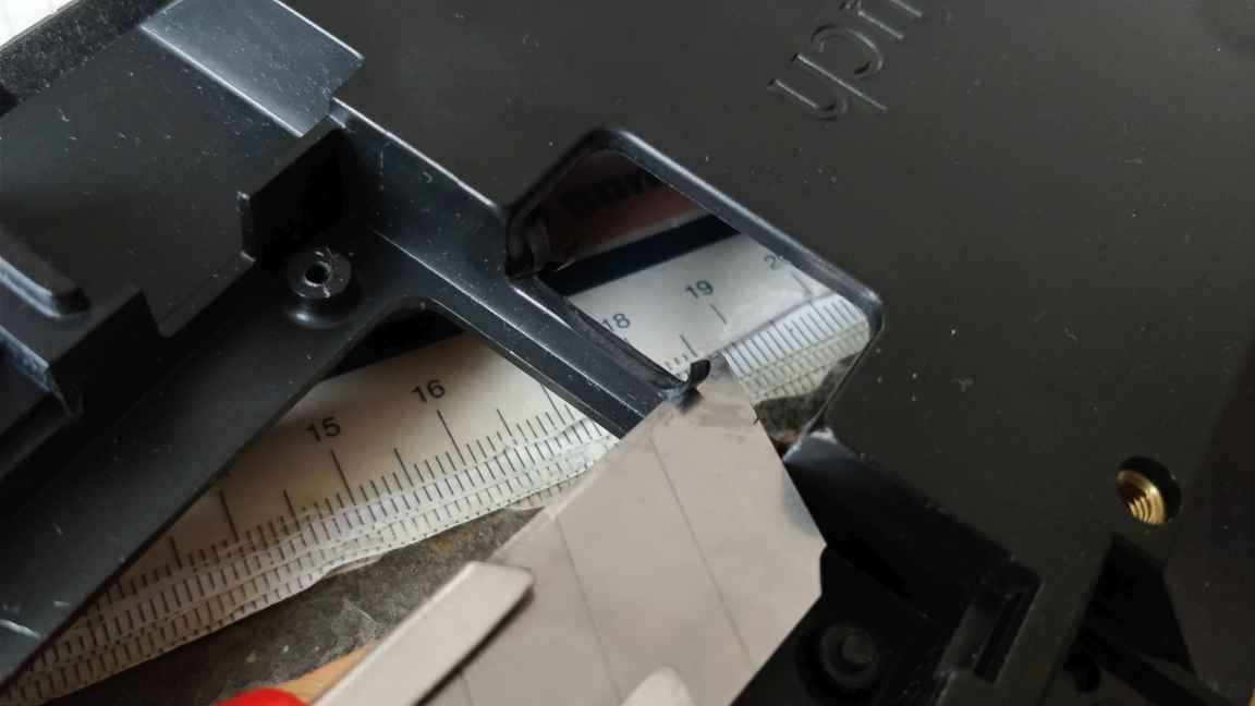
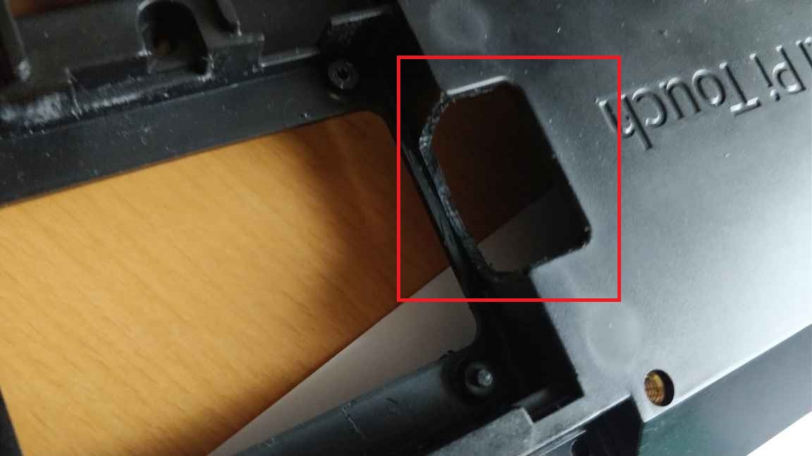
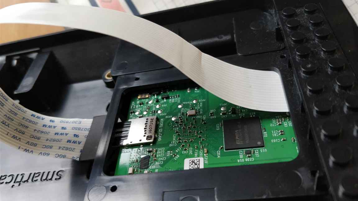
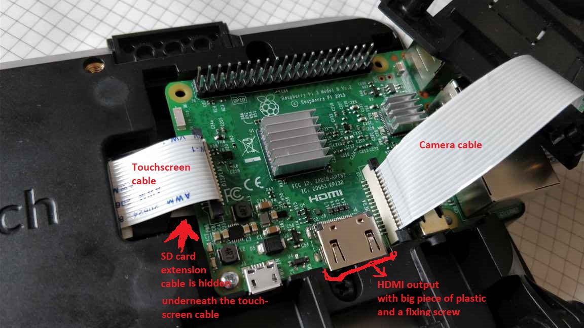
After cutting and removing parts of the edge of the Raspberry Pi area, the placement of the Raspberry Pi went much smoother. Still, the board got a little bit stuck with the unused USB port of the Touchscreen board, but it was possible to fix the Pi. A gentle pressure on the board’d left down corner put everything back to the right order. The SD cable leaves the case directly above/underneath the USB ports of the case. It does not look very pretty, although it allows to use all 4 USB ports. So it worked pretty fine for me. If you rely on cleaner version, then this alternative cable with a smaller male plug might be a solution. I have not tested it and reviews on Amazon are mixed, so I don’t know if this really works…
My failure to extend the HDMI output
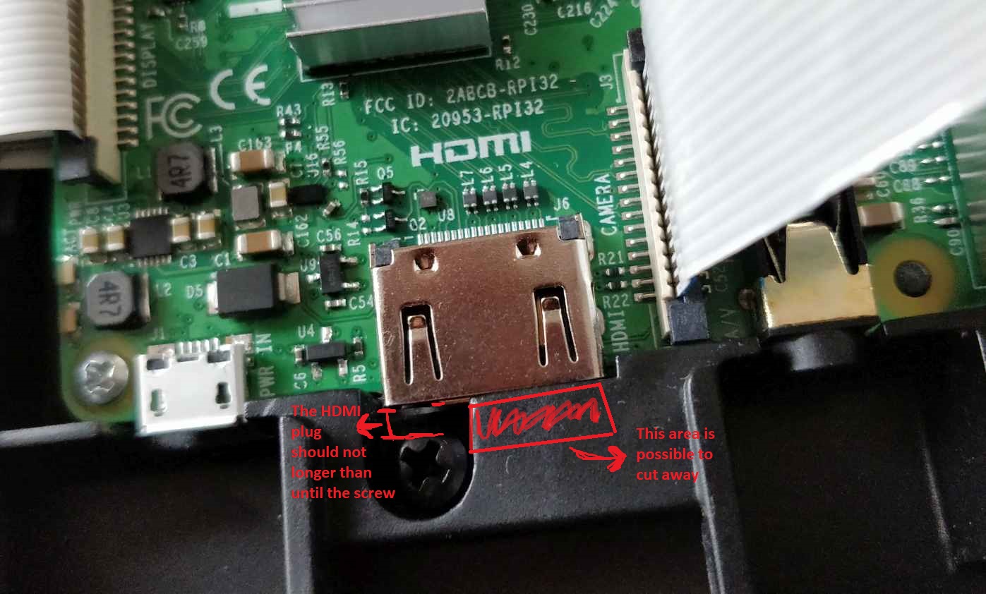
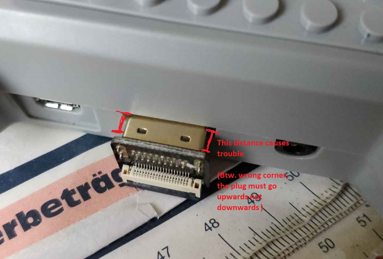
As already mentioned in the beginning of my blog post, the HDMI output extension did not work out for me. The HDMI output is blocked with a massive piece of plastic. Even worse, a fixing screw is also placed in front of the HDMI output. Only a very thin HDMI cable could solve that issue of a limited space. My approach of buying a HDMI FPV adapter cable with a 90° degree corner connector was the right way to go. Keep attention that you buy the right corner direction. I bought accidentally the wrong corner (correct version) … This was also one reason of my failure. The other reason was again the length of the male plug. The plug sticks out a few mm too much (0.3- 0.5cm). Such HDMI cables are often used on aerial drones or other RC vehicles within its limited space. I will do some further research on this issue. Maybe there is a chance to get a short/smaller male plug and solder the connector to this super flat HDMI cable.
If in the future the HDMI output won’t work due to the SmartiPi Touch case limits, then an visual output via GPIO Pins could be an interesting solution. The disadvantage of this solution is the loss of GPIO Pins and a lower analog VGA signal. However, if you don’t need the GPIO Pins and no Full HD resolution, then this GERT’S VGA ADAPTER might be a cool solution.
Off Topic experimentations
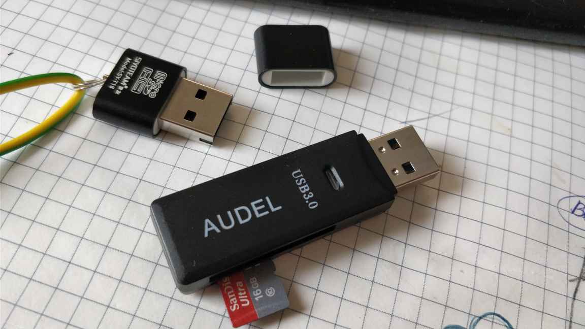
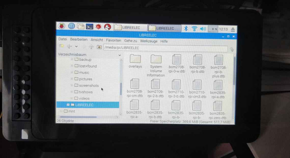
Beside pimping my case, I also tested two USB MicroSD Card readers. Sometimes, I create my own Raspberry Pi images with pre-configured webserver infrastructure. On my Windows 10 machines, I had problems to edit some of these image files (shrinking images), and/or change some config directly on the SD Card. My small portable Raspberry Pi might help me with these kinds of tasks. Furthermore, I don’t have to be scared to destroy my boot table. Here are my two SD Card readers, which worked very good for me.
I hope this blog post gave some inspiration and motivations to pimp your SmartiPi Touch case. It would be very nice if yow can share your experiences with case modding. Thank you very much and Happy Coding!


5 Comments
Some nice tool for display / kiosk apps
https://www.screenly.io/ose/
Sometimes it nice to run an grapical/ui app from another linux client/device. This tutorial explained very well how to transmit the x11 display information from linux computer (e.g. Raspberry Pi) to a windows machine. I am pretty sure that the display stream could be streamed also to another source… for instance a large screen or projector with a connected raspberry pi as display stream receiver.
https://blog.ropnop.com/configuring-a-pretty-and-usable-terminal-emulator-for-wsl/
https://www.makeuseof.com/tag/raspberry-pi-chromecast/
https://github.com/Pat-Carter/stream2chromecast/issues/47
https://developers.google.com/web/updates/2018/04/present-web-pages-to-secondary-attached-displays
Another great portable screen project with a Raspberry Zero. Coulde be like a Server in the Pocket
http://www.recantha.co.uk/blog/?p=18689
https://blog.hackster.io/pi-console-pops-into-place-for-use-30d5cdd42773
Another great article about Multi-Camera setup with the RaspberryPi
http://www.arducam.com/multi-camera-adapter-module-raspberry-pi/
The RasPad – a Raspberry Pi Tablet version – seems to be a wonderful alternative to my setup
https://www.raspberrypi.org/magpi/raspad-review/
https://blog.hackster.io/hands-on-the-sunfounder-raspad-raspberry-pi-tablet-f3256b9cebe0
https://hackernoon.com/raspad-review-turn-your-raspberry-pi-into-a-tablet-499579033214
https://www.sunfounder.com/ -> Webshop
Auf Deutsch
https://tutorials-raspberrypi.de/raspberry-pi-tablet-raspad-selber-bauen-testbericht/